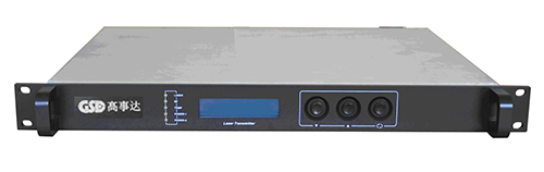
product description:
GSOR-1 is the company/s latest high-end second output CATV network optical receiver, the unit before all-GaAs MMIC amplification stage after stage of GaAs amplifier module, optimized circuit design, coupled with the company more than a dozen years of professional experience in the design, leaving the machine to achieve a high performance. MCU control digital display of the parameters, so that the project is particularly convenient debugging, is to build a CATV network mainstream models.
Features:
High responsivity PIN photoelectric conversion tube.
Route optimization design, SMT production process, optimizing the whole signal path, optical signal transmission more smoothly.
Professional RF attenuation chips, RF attenuation and equalization good linearity and high accuracy.
GaAs amplifier parts, doubling the output power, high gain and low distortion.
MCU control the whole work, LCD display parameters, easy and intuitive operation and stable performance.
AGC excellent characteristics, input optical power -9 to + when 2dBm, the output level remains unchanged, CTB, CSO basically unchanged.
Reserved data communication interface, can be connected with network management responder class Ⅱ, access management systems.
Technical Parameters:
|
project
|
unit
|
Performance parameters
|
|
Received optical power
|
dBm
|
-9 ~ +2
|
|
Optical Return Loss
|
dB
|
>45
|
|
Light-receiving wavelength
|
nm
|
1100 ~ 1600
|
|
Optical Connector Type
|
|
FC / APC, SC / APC or specified by the user
|
|
C/N
|
dB
|
≥ 51 (-2dBm input)
|
|
C/CTB
|
dB
|
≥ 65
|
Output level 108 dBuV,
When balanced 6dB
|
|
C/CSO
|
dB
|
≥ 60
|
|
Frequency Range
|
MHz
|
45 ~862/1003
|
|
Band flatness
|
dB
|
±0.75
|
|
Nominal output level
|
dBμV
|
≥ 108
|
|
Maximum output level
|
dBμV
|
≥ 114
|
|
Output Return Loss
|
dB
|
≥16
|
|
Electronically controlled range equalizer
|
dB
|
0~10
|
|
Electronically controlled attenuation range
|
dBμV
|
0~20
|
|
Power consumption
|
VA
|
≤ 30
|
|
Dimensions
|
mm
|
483(L)╳ 345(W)╳ 44(H)
|
Ordering Guide:
|
GSOR-1
|
0
|
0
|
0
|
|
GSD Indoor Optical Receiver Model
|
8: 862 MHz Bandwidth
1: 1GHz Bandwidth
|
1: one output
2: Two-way output
|
FC:FC/APC
SC:SC/APC
|
Failure Analysis:
|
Fault phenomenon
|
Fault phenomenon
|
Solution
|
|
Image light junction has obvious highlight of textured or large particles, but the image background is very clean.
|
Optical receiver input optical power is too high, the output power level of the optical receiver module is too high, the deterioration of the RF signal indicators.
Poor optical transmitter input RF signal indicator itself.
|
1. Check the input optical power within, and make appropriate adjustments to the predetermined range; or adjust the attenuation value of the light receiver, to reduce the output level, to improve the index.
2. Check the front room light transmitter RF signal indicators, and make appropriate adjustments.
|
|
Image light junction has significant noise.
|
Optical receiver input optical power is not enough, causing the carrier to noise ratio decreases.
Fiber optic adapter union or optical receiver is contaminated.
Optical transmitter input RF signal level is too low, the laser modulation system is not.
System Link signal carrier to noise ratio index is too low.
|
1, received optical power of the inspection light junction, and to make appropriate adjustments to the prescribed range.
2, through fiber optic connectors or adapters and other cleaning methods,
Resume light contacts received optical power.
3. Check the input optical transmitter RF signal level,
And adjust to the equipment required input range. (Fewer than 15 channels, should be higher than the nominal value.)
4, with a spectrum analyzer to check the system link carrier to noise ratio, and make appropriate adjustments to ensure link signal carrier to noise ratio (C / N) is greater than 51dB.
|
|
Image individual light junction apparent random noise or pull road.
|
Light junction there is an open signal interference or strong interference signal intrusion.
|
1. Check whether there is light at the junction of strong interference sources, if possible replaceable light junction position, to avoid the impact of strong interference sources.
2. Check the light contacts the following cabling, shielding or whether there is the presence of RF connectors poor shielding effect.
3, tightly equipment cabinet, to ensure the shielding effect;
If possible, install the shield in light junction, and reliable grounding shield.
|
|
Individual light junction image appears one or two horizontal raceways.
|
Due to poor equipment or poor grounding power ground, causing power AC ripple interference.
|
Grounding condition of inspection equipment to ensure that lines each device are well grounded, and the grounding resistance should be <4Ω.
|
|
Received optical power junction of instability, there is a large continuous changes, the output RF signal is not stable; but the detection optical transmitter output optical power but normal.
|
Fiber optic connector type does not match, it may be APC-type connectors for PC-type connector, resulting in optical signal transmission can not be normal.
Optical fiber connector or adapter is seriously polluted, or adapter is damaged.
|
1, type checking optical fiber connector heads, to be elected
APC fiber optic connector type used to ensure the normal transmission of optical signals.
2, cleaning the contaminated union or fiber optic adapter.
3. Replace damaged adapter.
|